DIY Codings Kid Ai Smart Stem Educational Microbit Robot Kit Teaching Toys for Student

Still deciding? Get samples of $ !
Order Sample

Product Description

Overview
Basic Info.
Model NO.
181018
Delivery Time
7 Days
Service
OEM/ODM Acceptable
Transport Package
Plastic
Specification
437 x 320 x 200 mm
Origin
China
HS Code
90230090
Packaging & Delivery
Package Size
49.00cm * 34.00cm * 25.00cm
Package Gross Weight
5.500kg
Lead Time
7 days (1 - 20 Pieces)
15 days (21 - 100 Pieces)
To be negotiated ( > 100 Pieces)
DIY Codings Kid Ai Smart Stem Educational Robot Kit Teaching Toys for Student
Product Description
12 in 1 Robotstorm STEAM Robot Kit

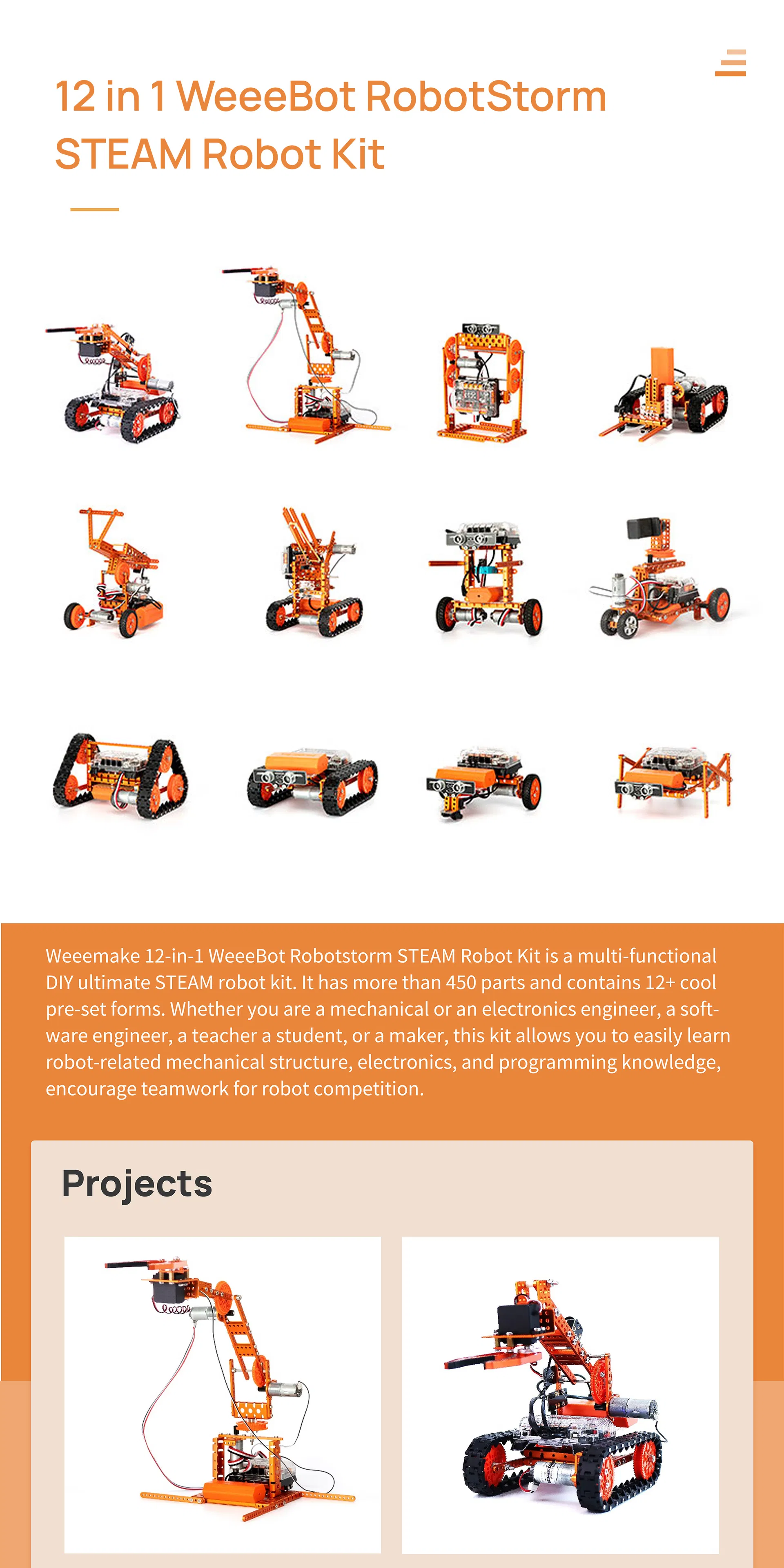
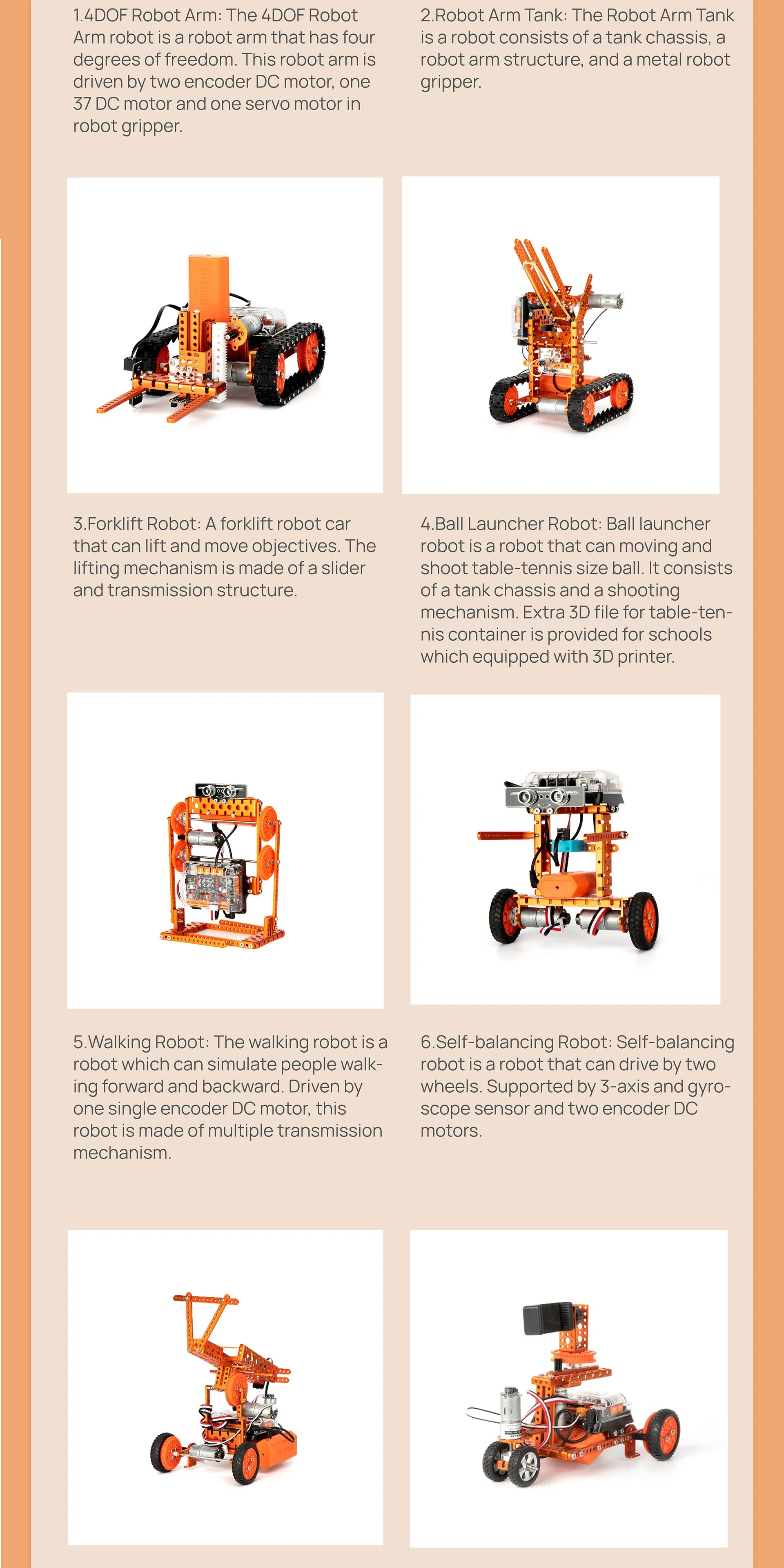
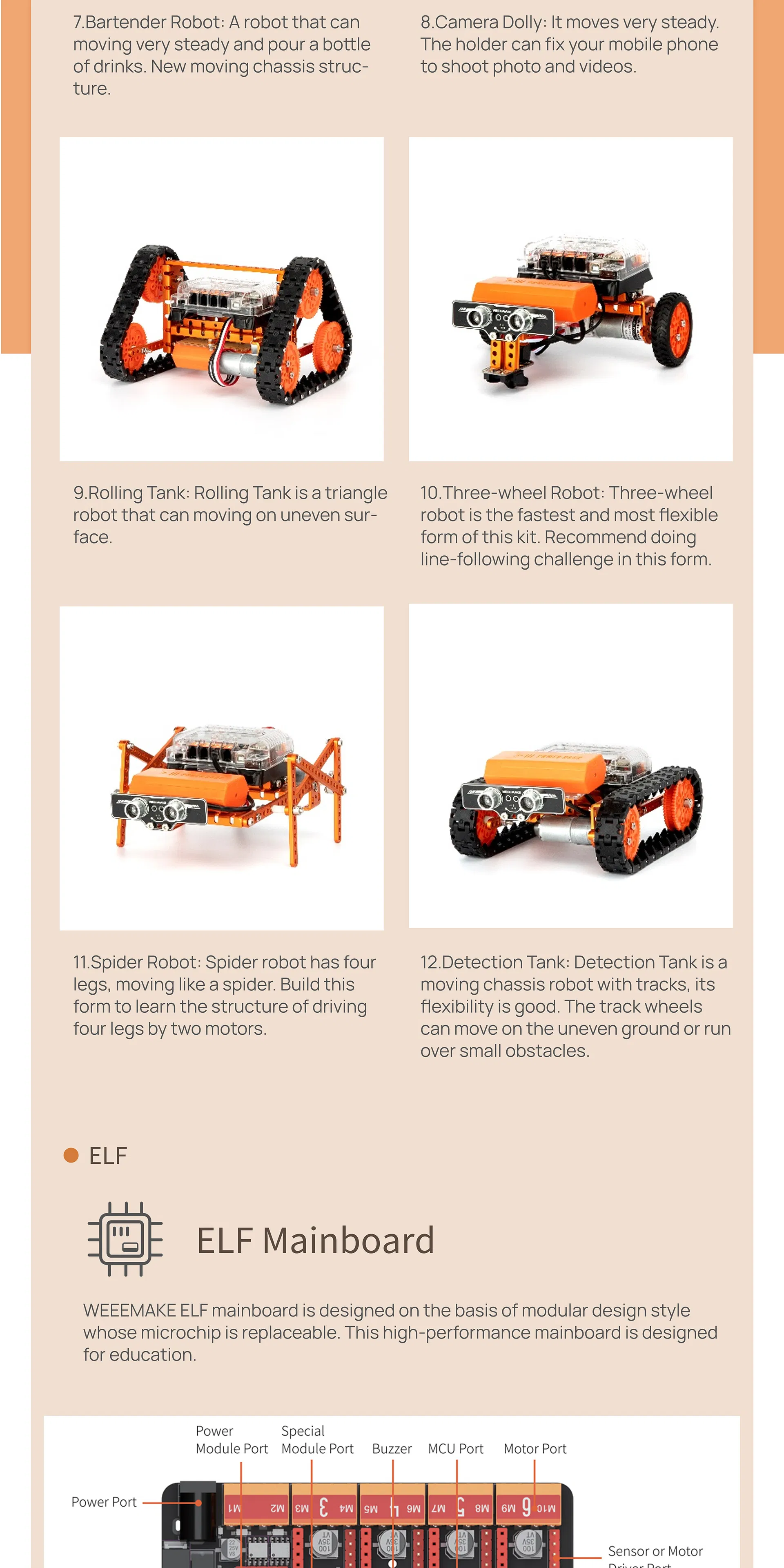
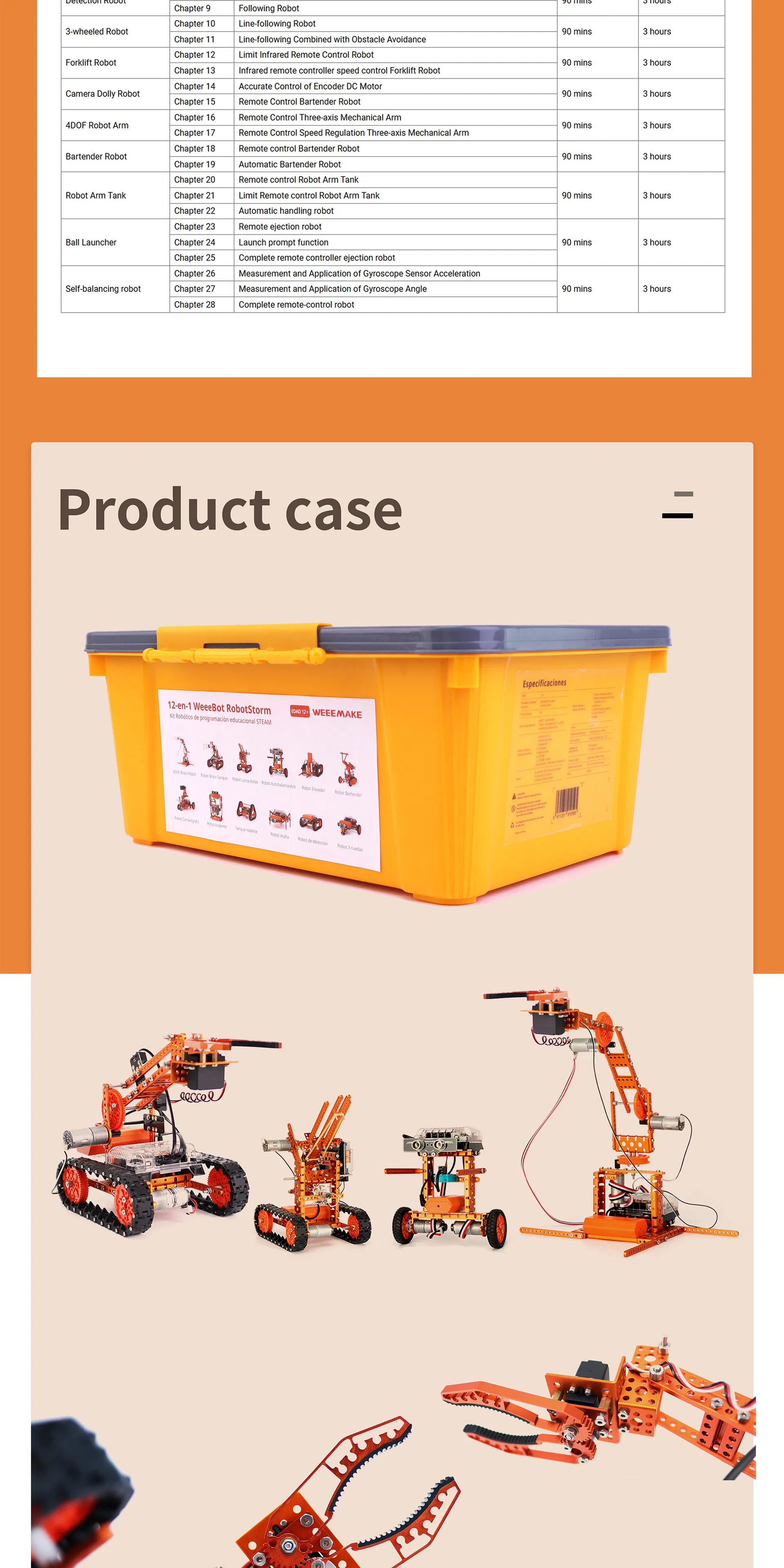
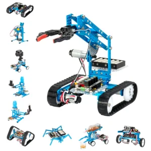
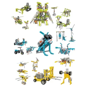
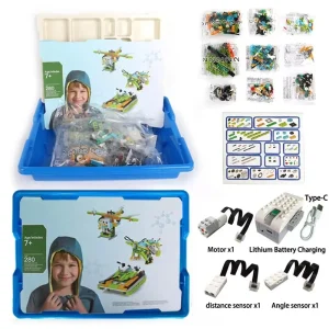
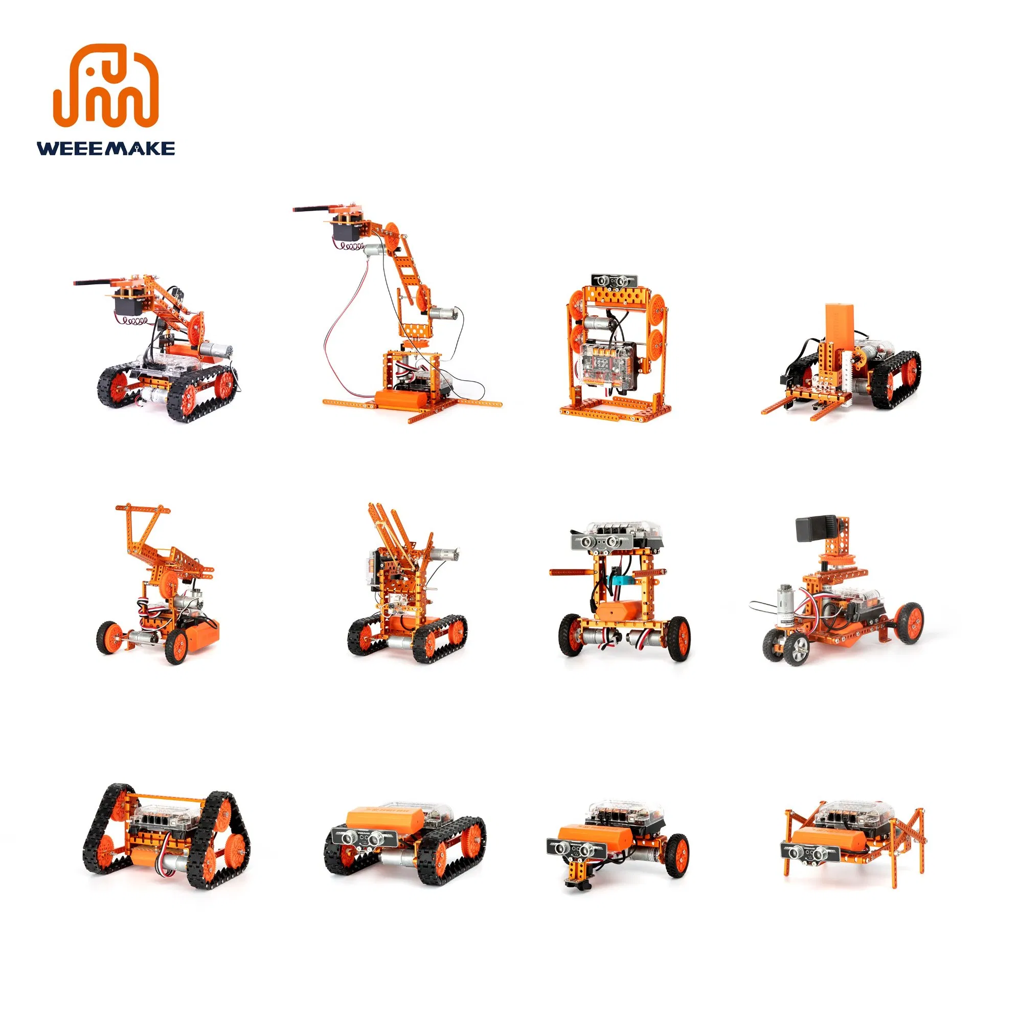
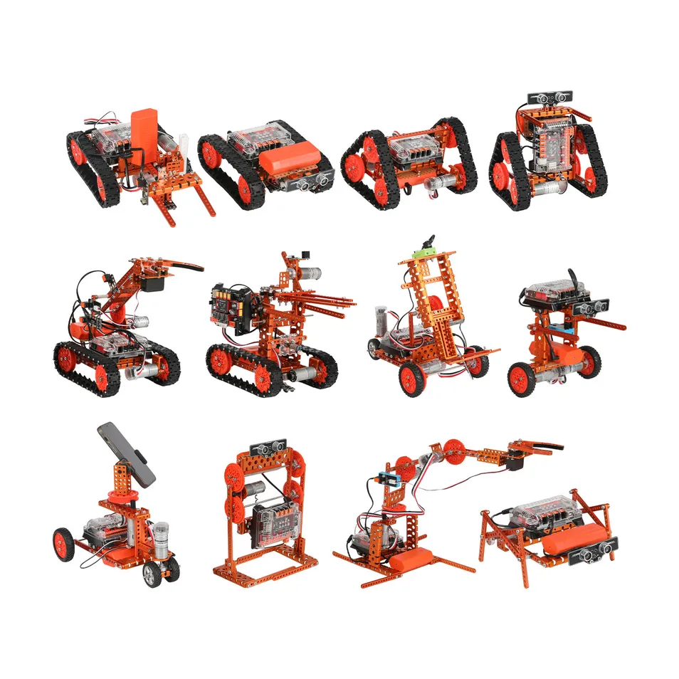
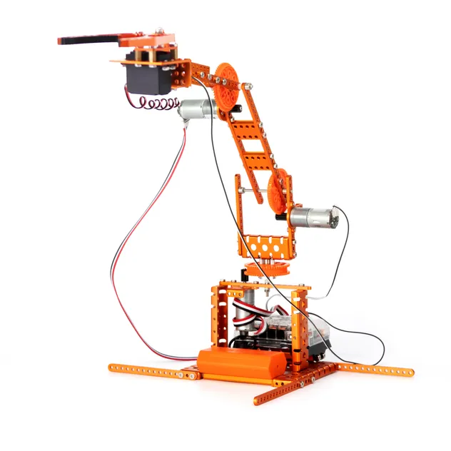
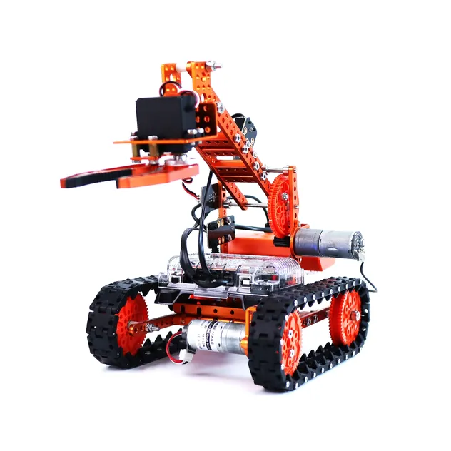
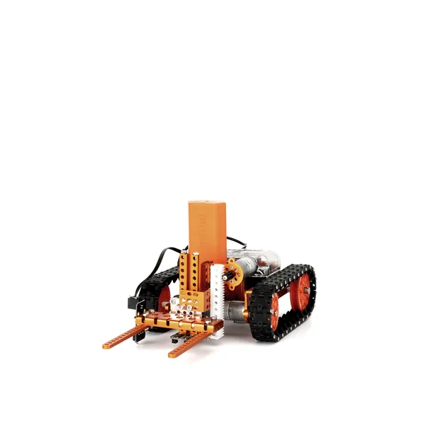
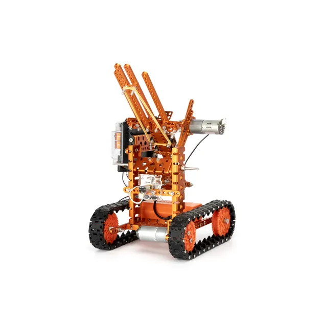
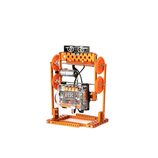
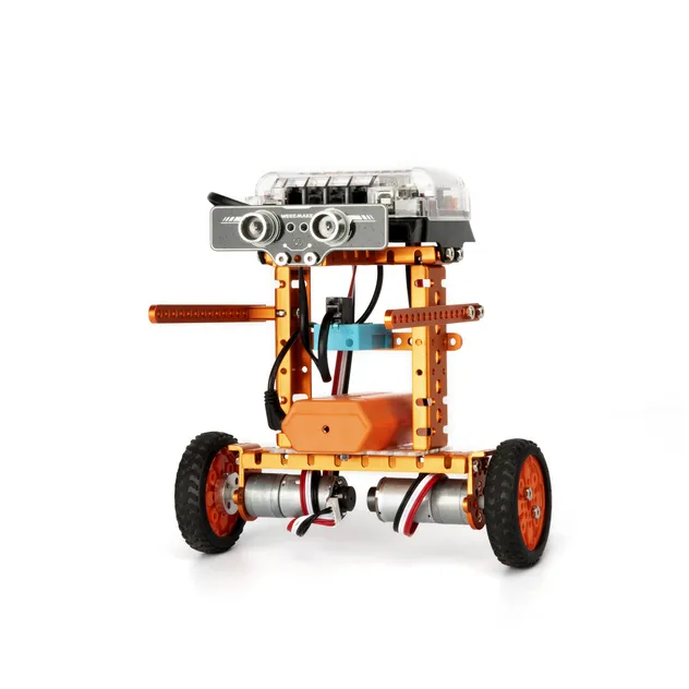
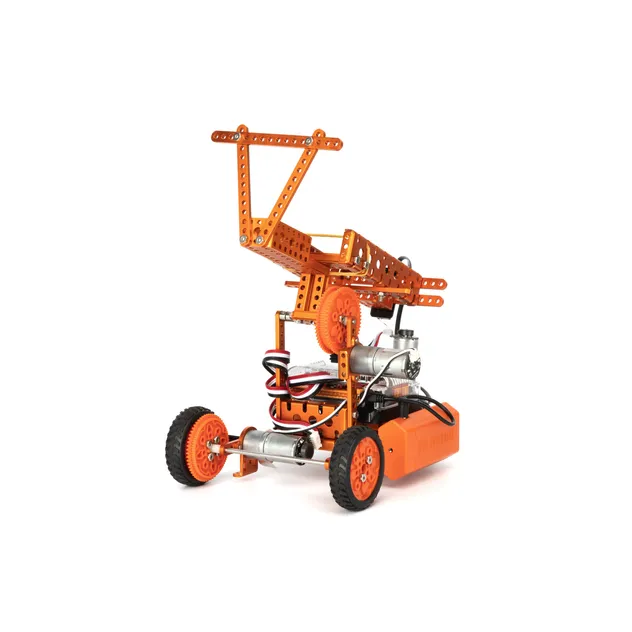
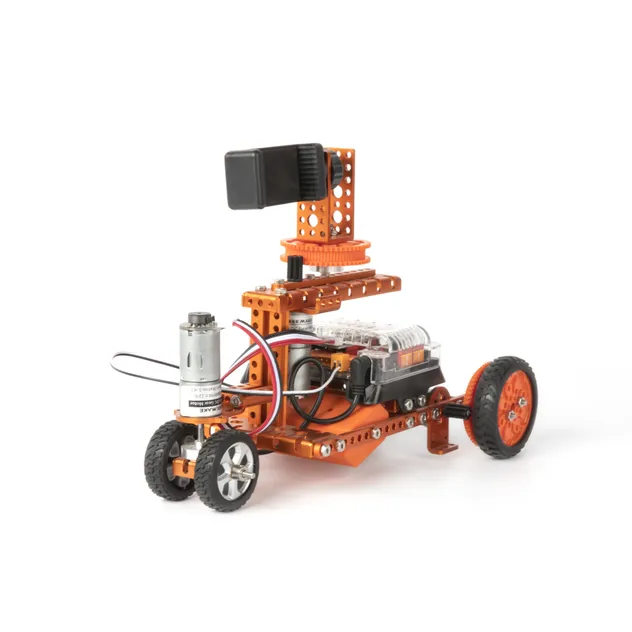
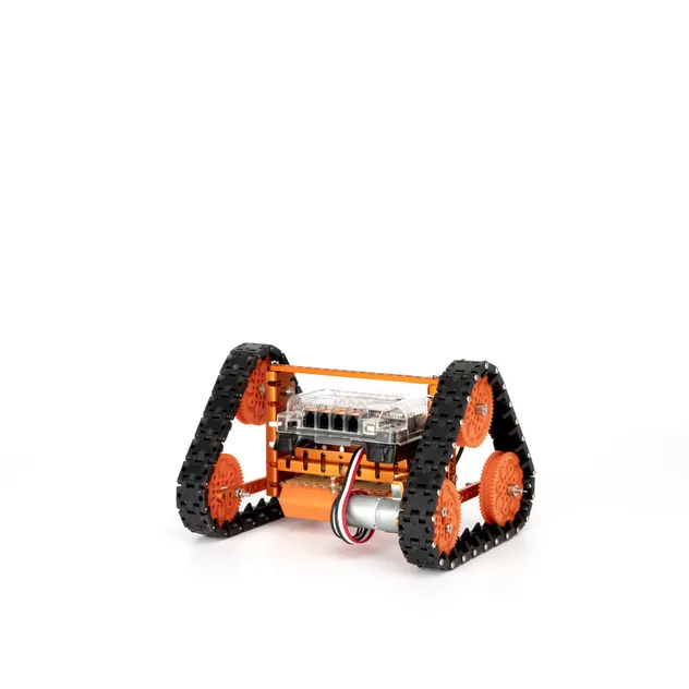
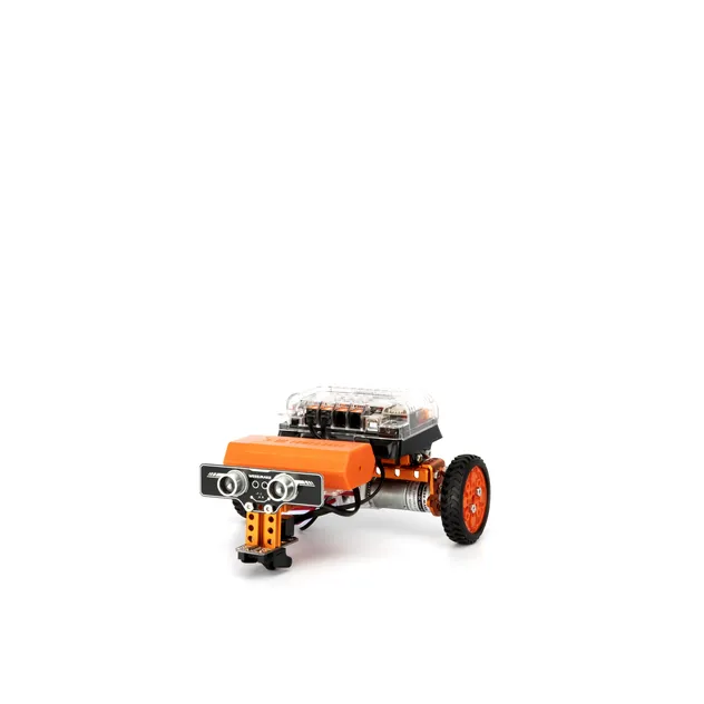
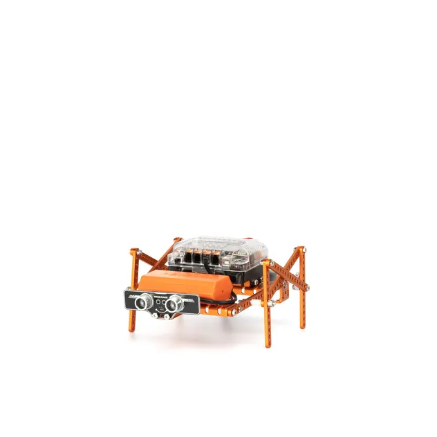
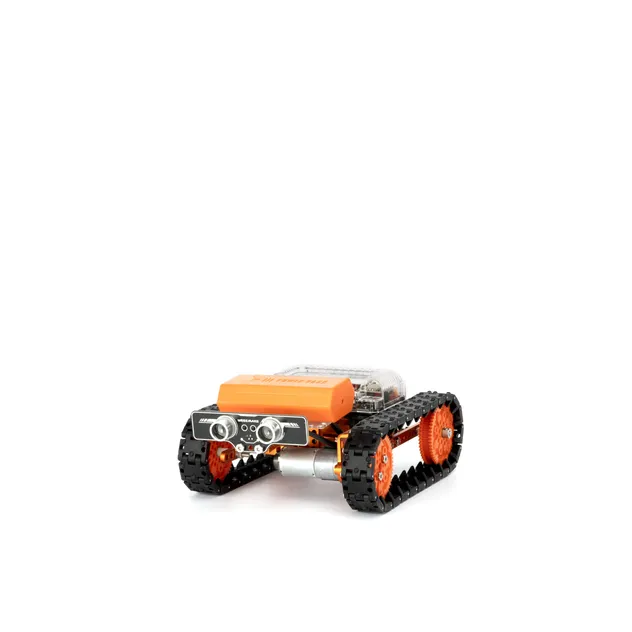
This 12-in-1 STEAM Robot Kit is a multi-functional DIY ultimate STEAM robot kit. It has more than 450 parts and contains 12+ cool pre-set forms. Whether you are a mechanical or an electronics engineer, a software engineer, a teacher, a student, or a maker, this kit allows you to easily learn robot-related mechanical structure, electronics, and programming knowledge, and encourages teamwork for robot competitions.

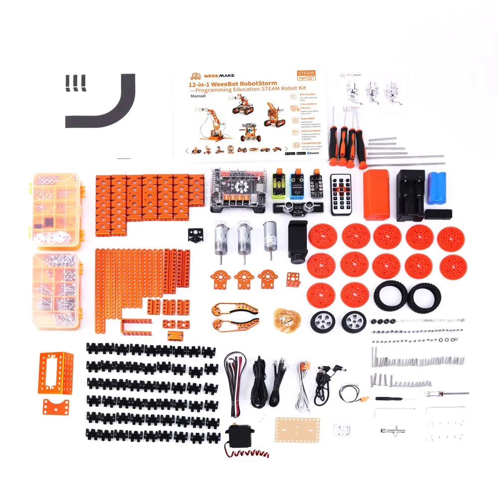
This kit is a powerful parts library consisting of more than 450 parts. With heavy-duty mechanical parts such as beams, plates, brackets, gears, grippers, tracks, shafts, wheels, and easy-to-use electronic modules like the mainboard, RGB ultrasonic sensor, Line-following sensor, gyroscope sensor, limit switch, RGB LED-8 module, light sensor, sound sensor, buzzer, IR receiver, Bluetooth module, and Bluetooth dongle, you can get an enhanced hands-on experience on 12 different robot setups programmable wirelessly.

STEAM Robot Kit
ELF Mainboard

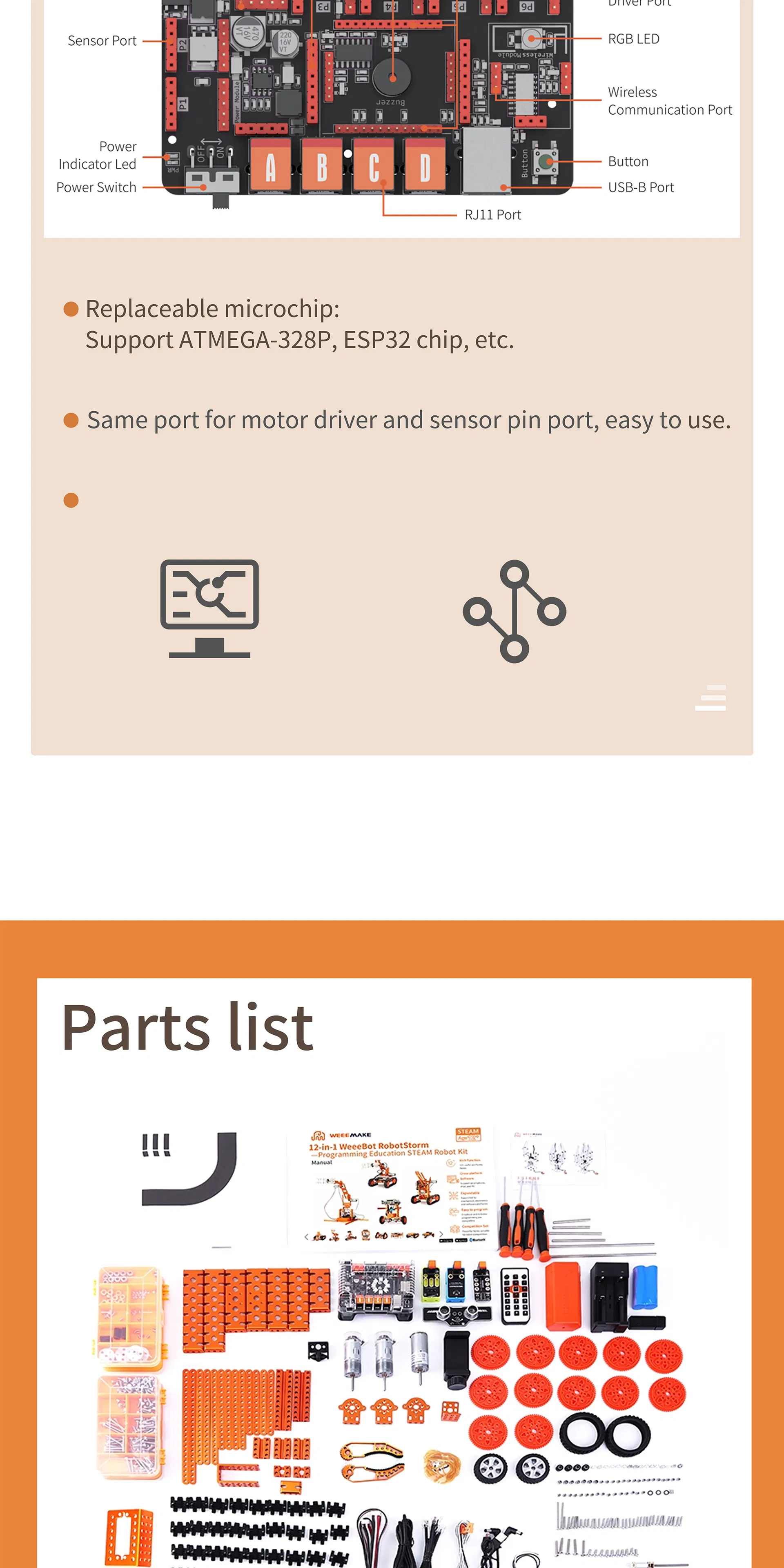
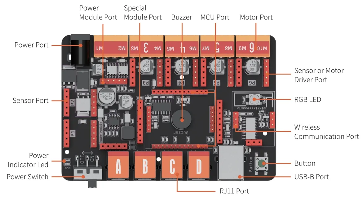
The ELF mainboard features a modular architecture with a replaceable microchip. This high-performance board is optimized for educational environments.

  • Replaceable microchip design (Supports ATMEGA-328P, ESP32, etc.)
  • Unified port structure for motor drivers and sensors for easy wiring.
  • Supports graphical software and code-based programming.
ELF Mainboard Details
Specifications
Operation Voltage 6-12V
Wiring Ports 1x MCU port (ATmega 328p or ESP32)
4x RJ11 port
2x DC motor port
6x pin conversion port (4 of which can serve as stepper/encoder/DC motor ports)
1x Wireless Communication port (Bluetooth 2.4G)
1x USB port (type B)
Onboard Electronics 1x Buzzer
1x Button
1x RGB LED
Software Support Graphical Programming Software (Scratch 3.0 base)
Arduino IDE
Specification Overview
Certifications
Certification Documents Part 1
Certification Documents Part 2
Our Exhibition
Robot Exhibition Events
FAQ
Q: When I turn on the robot, it has no response. Why?
1. Low voltage: Please recharge the batteries or replace them with new ones.
2. Incorrect installation: The batteries might be installed with reversed polarity (+/-).
3. Incorrect wiring: Please inspect the connection on the battery holder or the motor.
Q: When I control the robot to move forward, it moves backward. How can I fix this?
The wiring of the motor is connected in reverse. Please reconnect the motor wires with the opposite polarity.
Q: How can I program my robot or restore its factory settings?
Please download the programming software on the official resource page, connect the robot to your PC using the USB cable, select the corresponding serial port "COM x" and the mainboard type within the software to start coding.
The firmware menu offers three main options:
- "Online Firmware" allows live testing where the robot responds immediately.
- "Factory Firmware" restores the default factory program and configurations.
- "Mobile Firmware" enables control and programming via the companion mobile application.
Q: I cannot connect the robot to the computer via USB or wireless connections. How do I fix it?
This typically happens if the computer lacks the mainboard driver. Please navigate to the "Help" menu inside the programming software, install the required driver, restart the robot, and try connecting again.
Q: Why is the robot unable to move under USB power supply alone?
The USB power supply only provides enough current to power the microchip and onboard sensors. To drive the DC motors or servos, you must connect the batteries and toggle the power switch to the ON position.
Q: Why doesn't the Line-following Sensor work?
1. Ensure the distance between the Line-following sensor and the surface map is kept between 1-2cm for optimal detection.
2. Avoid operating the line-following function under strong direct ambient light, as it interferes with the optical sensors.
3. Make sure to use non-reflective materials when printing or creating your custom line-following maps.

Related Products